In this article, you will learn about hydraulics flow control valve, basic jobs, the principle of working, construction and some type of hydraulic flow control valve.
Definition of a flow control valve
Definition: A hydraulic flow control valve is a hydraulic device which controls the flow rate by giving a definite amount of passage to the flow of hydraulic fluid. Basically, it controls the speed of actuators or complete operation in the hydraulic system. A hydraulics flow control valve has two main jobs.
- Speed regulation
- The e
qualisation of pressure fluctuation.
A hydraulics flow control valve is also called a flow restrictor valve because it restricts the flow and allows the fluid in the desired flow rate. For example,

In this hydraulic circuit, consider when we start the pump and position the direction control valve in position B what will happen? The cylinders piston extend rapidly. This rapid movement can cause jerking in the system and the function will not smooth. So, we need something which can control the rapid movement. Therefore, we use hydraulics flow control valve or simply a flow restrictor.

Figure 2 is the symbol for flow restrictor. Various kind of flow restrictors are available and according to that symbols also differs. Above figure represents a constant flow restrictor or flow control valve. Now, see the solution for the above-mentioned problem.

When you place a flow restrictor in the system it will reduce the cross-section of the pipe and allow less hydraulic oil flowing per unit time. Because of less quantity of hydraulic oil flowing per second to the actuator, the actuator moves slowly and you can control the speed.
Type of hydraulic flow control valve
- onstant flow control valve
Adjustable flow control valve
Constant flow control valve
A constant flow control valve controls the flow rate but it will be fixed forever. We can not change the cross-sectional area and hence, we can not change the flow rate. In the above figure 3, The speed of the actuator will be fixed irrespective of load and if the load increased again operation will not smooth. So, as per changing a load the design also changes.
Adjustable flow control valve
An adjustable flow control valve is also controlling the flow rate of hydraulic fluid but we can change the cross-sectional area and hence, we can change the flow rate. If a load is increased then we can reduce the cross-sectional area and can change the speed of actuator and operation will be smoother. Figure 4 shows the symbol of a variable flow control valve.

Construction of Flow control valve
Flow control Valve can be designed in various ways but the basic designs are
- Throttle type- It can be a constant or variable flow control.
- Orifice type- it can only be a constant type.


In throttle type, there is an opening for flow rate limitation and it can be adjusted by a screw. But in orifice type, there is just an orifice which limits the flow rate and we can not change the size of an orifice.
Influence of pressure fluctuation on speed
With restrictor (flow control) valve either constant or variable type, minor pressure fluctuation can cause flow rate changes and speed of operation. For example,

Consider a rope winch driven by hydraulic power. The speed of winch is controlling by a variable flow restrictor. When a load is not changing or single user then speed will nearly constant but if additional users and also changing loads in the system can cause pressure fluctuations. when load increase in winch pressure will increase on the other hand addition of user (load in system) will decrease the pressure. So, pressure may change repeatedly in the system and also change the flow rate. The challenge is that the pressure in the system changes in an undefined way and not parallel. The motor will rotate with different speeds—and therefore the rope winch will too. But we do not want that. Ideally, a rope winch should always rotate at the same speed, rotational speed should remain constant even with pressure differences.
To achieve this, a pressure balance valve is added to a variable flow restrictor valve.

In this diagram, there will be some pressure drop due to flow restrictor when fluid is flowing. Let us consider the flow restrictor is preset at a particular pressure difference delta P( difference of pressure before and after restrictor valve). When the load at rope winch increase pressure will also increase after the flow restrictor and accordingly speed will effects.
Metering Throttle
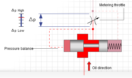
See figure 8 and 9, the increased pressure above the restrictor valve called a metering throttle here, acts via the control line on the spring side of the pressure balance. The piston of the pressure balance extends toward the left and releases more flow volume. The pressure in front of the metering throttle increases, and the preset pressure difference here, delta p, is restored. The pressure fluctuation was thus balanced. And the outlet pressure of the metering throttle stays unchanged despite the pressure fluctuation. This is also called Pressure compensated flow control valve.
This is all about Flow control valve/flow regulator valve/flow restrictor valve or throttle valve. Hope you understood. Comment below if you have any queries.